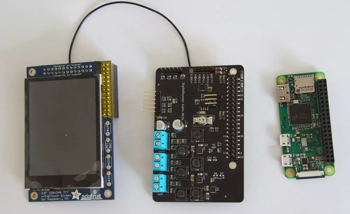
Assembly
How to mount
Actually assembly is not that hard. You have to solder some jumpers, a 40 pin 2.54mm female connector (and a wire for Raspberry Pi).
Required parts
Raspberry Pi Zero W (without soldered header)
Long (15mm) 2.54mm connection header to stack the extension boards on the Raspberry Pi (Digikey 3M156504-72-ND)
Adafruit PiTFT2.8” capacitive touch 1983
40 Pin Female Header 2,54mm for instance MPE Garry 094-2-040
Step by step
Please read the safety and environmental notes and check the schematic-mk3b.pdf. Think twice before soldering
The connector and the receptable
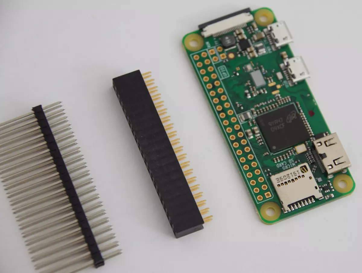
Solder the receptable (is this the correct term for “female” header?) on your raspberry Pi or Banana Pi. The receptable is on the top side, i.e. where the SoC is.
The solder jumpers
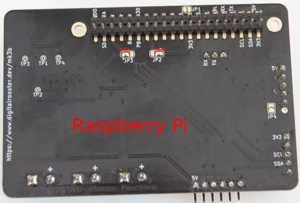
Make sure you solder the correct jumpers for Raspberry Pi OR Banana Pi (not both).
Example for Raspberry Pi
To connect the I2S lines to the correct pins you have to solder jumper JP2 and JP3 to position 1-2 (the small triangle marks pad 1)
You must not solder JP4 This jumper connects the back-light dimming to GPIO pin 12 which Raspberry Pi unfortunately uses for I2S bit clock. You have to solder a wire from J5 pin 6 to the back-light PWM control input of your display. Unfortunately the Raspberry Pi SoC BCM2708 has few PWM lines and
Do not solder JP1.
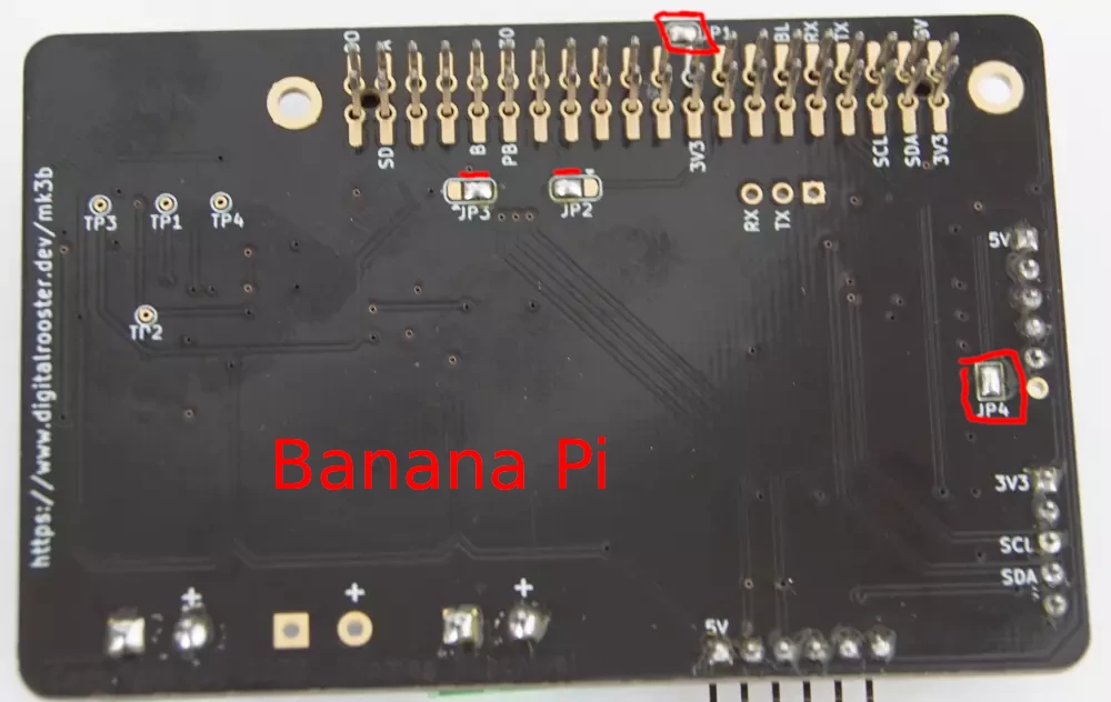
Example for Banana Pi
To connect the I2S lines to the correct pins you have to solder jumper JP2 and JP3 to position 2-3 (the small triangle marks pad 1)
You can/should solder JP4 This jumper connects the PWM output to the back-light pin of your PiTFT2.8” capacitive touch Some of the PiTFTs also have a solder jumper to enable back-light dimming.
You must solder JP1. This jumper is a workaround for Banana Pi. The Allwinner H2+ SoC unfortunately has no IRQ line on PC4. Adafruit designed the PiTFT to use pin 18 as IRQ for the touch sensor. This jumper maps PC4 (pin 18) to PL4 (pin 26) which has interrupt functionality.
The Back-light dimming (for Raspberry Pi
Since Pin 12 is already occupied we have to use a flying wire to connect the back-light dimming channel of the PWM led driver to the display.
Connect the red marked headers with the solder jumper of the PiTFT2.8

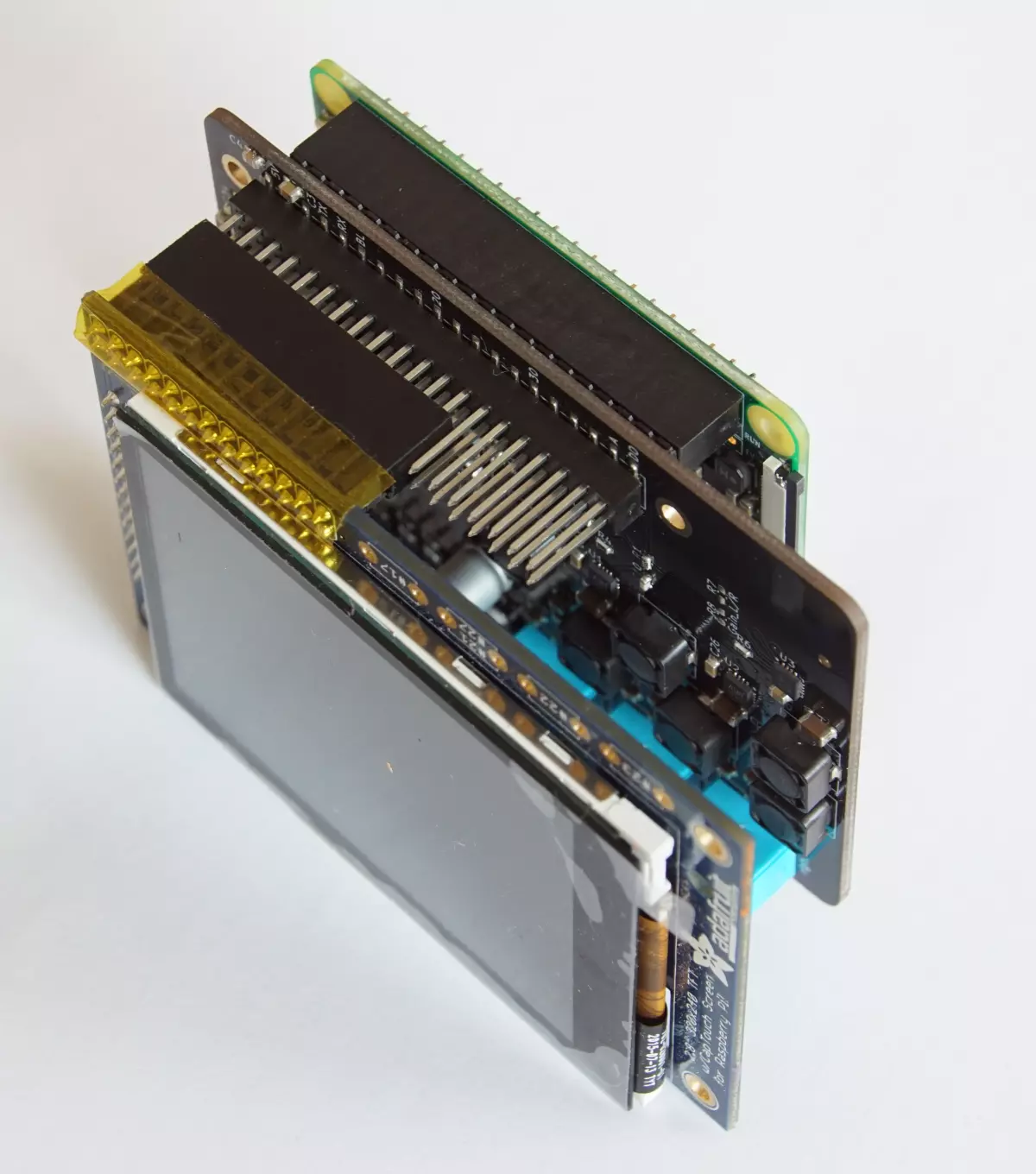
Mount it
You now have all parts in place. Just insert the long pin header with the long end to the front in your digitalrooster-mk3b and put the parts together.
