DigitalRooster MK3b

Introduction
You can get the DigitalRooster-Mk3b from tindie.com!
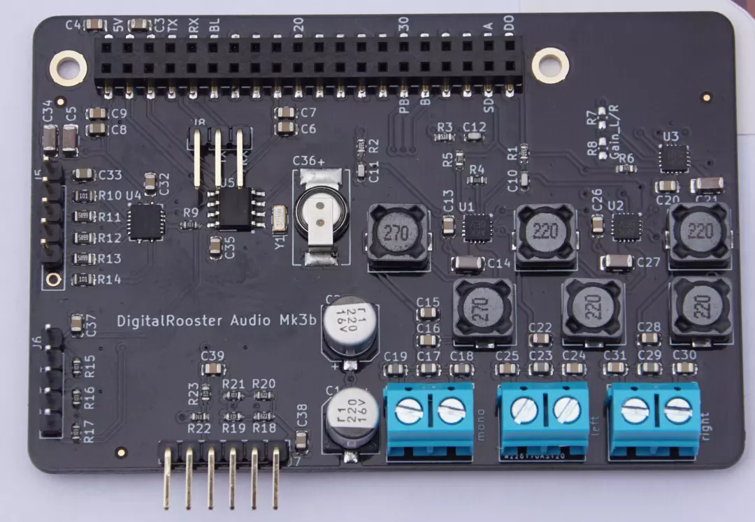
The hardware is designed to works both with Raspberry Pi Zero W and Banana Pi M2 Zero. To work with any of these two boards requires soldering some jumpers.
Note: The Mk3b-extension board is a module without independent function, and is exclusively intended for development or education purposes under laboratory conditions. For use or operation specialist knowledge is required. Please observe the necessary regulations and the general safety and environmental notes
Schematic
The schematic PDF contains some additional notes on
optional components and solder jumpers.

Solder Jumpers
Warning: Soldering can cause injuries and requires some skills. The solder iron is hot and solder fumes are hazardous! Please also read the safety and environmental notes

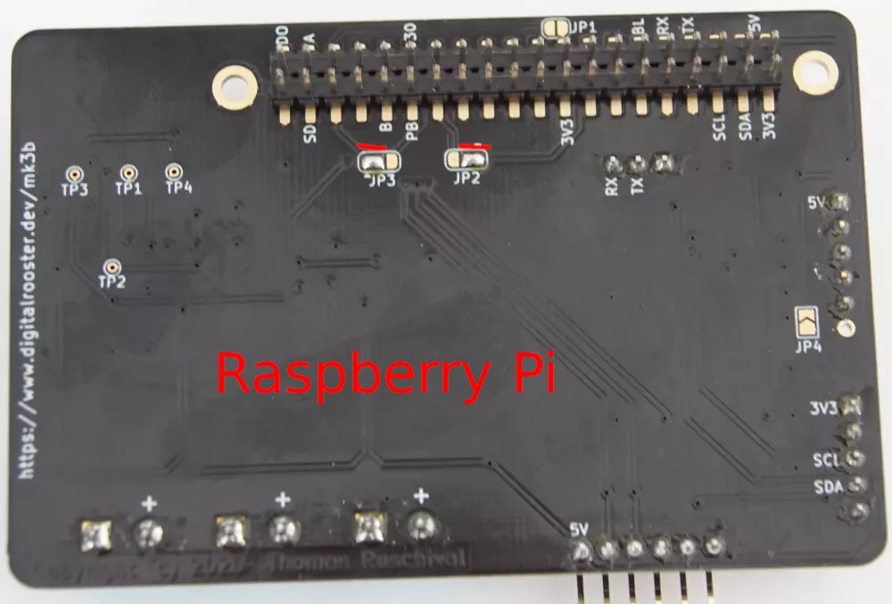
Raspberry Pi
To connect the I2S lines to the correct pins you have to solder jumper JP2 and JP3 to position 1-2 (the small triangle marks pad 1)
You must not solder JP4 This jumper connects the back-light dimming to GPIO pin 12 which Raspberry Pi unfortunately uses for I2S bit clock. You have to solder a wire from J5 pin 6 to the back-light PWM control input of your display. Unfortunately the Raspberry Pi SoC BCM2708 has few PWM lines and
Do not solder JP1.

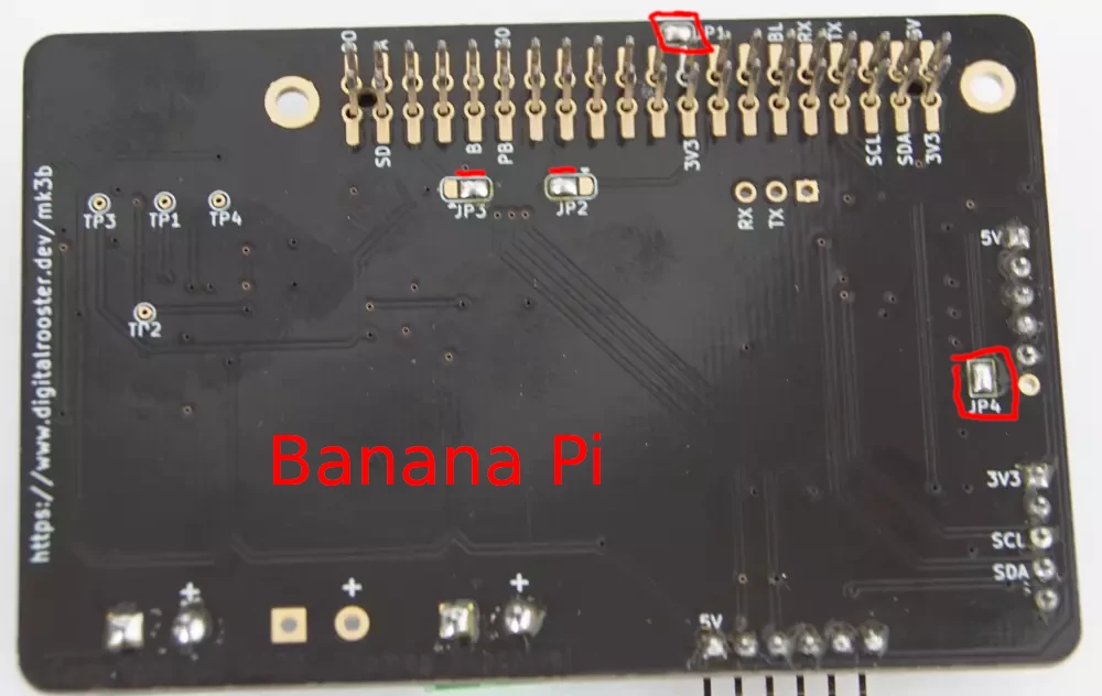
Banana Pi
To connect the I2S lines to the correct pins you have to solder jumper JP2 and JP3 to position 2-3 (the small triangle marks pad 1)
You can/should solder JP4 This jumper connects the PWM output to the back-light pin of your PiTFT2.8” capacitive touch Some of the PiTFTs also have a solder jumper to enable back-light dimming.
You must solder JP1. This jumper is a workaround for Banana Pi. The Allwinner H2+ SoC unfortunately has no IRQ line on PC4. Adafruit designed the PiTFT to use pin 18 as IRQ for the touch sensor. This jumper maps PC4 (pin 18) to PL4 (pin 26) which has interrupt functionality.

FAQ
During boot I see errors for failing oscillator of the real time clock!.
You may come across this message[ 0.789186] bq32k 1-0068: Oscillator Failure. Check RTC battery. [ 0.796005] bq32k 1-0068: Enabled trickle RTC battery charge. [ 0.802898] rtc rtc0: read_time: fail to read: -22This is not a false alarm. It happens when you plug in your board and the super cap has not yet been charged and hence the RTC is not yet backup powered. This message will go away after some time. The trickle charger takes some hours to charge the supercap C36.
